
Categories
Recent News & Blog
Share With
How to install clearvu fencing begins with measured boundaries, matching components, and a practical construction sequence. BMP supplies welded security mesh, posts, clamps, and gates for different installation systems. An approved drawing determines which components belong together.
Installers should never assume every ClearVu panel uses identical post centres or concrete footings. Ground conditions, panel geometry, and gate loads change the structural requirements. Safety and accuracy matter before the first hole.
BMP Clear View Fence Panels include flat and formed options with different fixing arrangements. Compare the supplied components against the drawing before delivery to site. Incorrect bay spacing can affect an entire boundary.
A panel measuring 3305 mm wide may belong to a system with 3390 mm post centres. That example assumes specific tapered posts and clamps. Another panel width requires its own approved setting-out dimension.
Do not transfer an example spacing to a new model without verification. A 2515 mm flat mesh panel needs its own connector and post schedule. Measure centre-to-centre positions, not simply the steel sheet width.
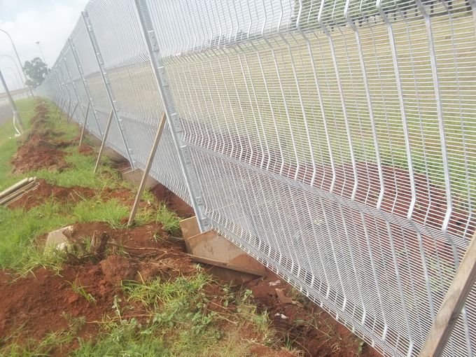 |
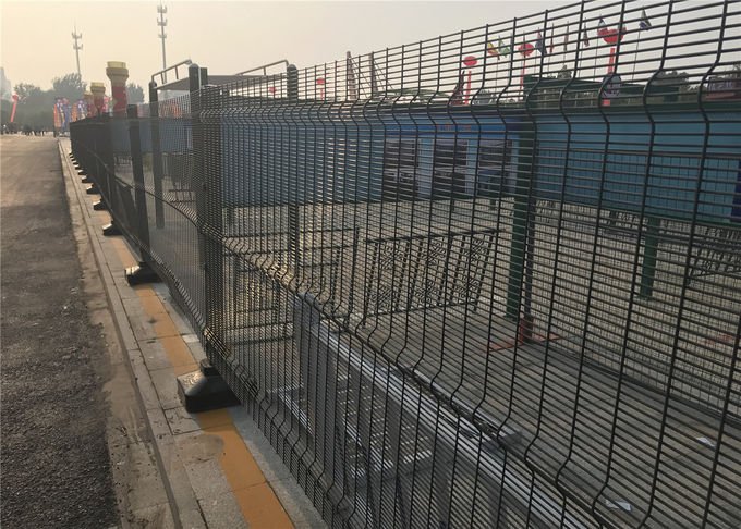 |
| Original BMP installation photo: observe the fence alignment, vertical supports, and finished top configuration. | Original BMP site photo: compare panel placement with the intended concrete foundation and fixing sequence. |
Organise tools and hardware before excavation begins. Missing clamps or incorrect bolt sizes can halt installation after concrete work. Check every package against the manufacturer’s bill of materials.
Personnel should verify lifting capacity for tall or heavy panels. Sharp cut edges can injure workers during handling. Mechanical equipment also needs competent operators and exclusion zones.
Identify mesh pitch, finished dimensions, coating type, and the number of horizontal bends. ClearVu Fence Panels appear in several product families. Match each bundle to its drawing revision.
Inspect tapered posts separately from square or I-shaped supports. Their attachment faces cannot automatically share the same hardware. Prepare an identification label for every material group.
Walk the entire proposed fence line before placing stakes. Record corners, changes in level, retaining walls, trees, drainage routes, and vehicle entrances. Check lawful boundaries and local permissions where required.
Contact the relevant utility owners before excavating near buried cables or pipes. Mark verified service locations on the site drawing. Avoid mechanical excavation inside any required protection zone.
A slope can change the apparent ground clearance beneath rigid rectangular panels. Stepped installation preserves panel geometry but may leave triangular openings. Custom infill sections require factory approval.
Raked installation only suits panels and connections designed for the necessary angle. Never force a stiff welded panel into an unsupported shape. Maintain approved drainage paths along the lower boundary.
Set fixed reference points at both ends of each straight fence run. Locate gate openings and special corner posts before dividing the remaining line. This approach helps prevent awkward closing bays.
Use string or laser references to check alignment along the run. Mark each proposed post centre clearly. Record bay lengths and relevant survey levels.
Post centres follow the actual installed system, including clamp overlap and post geometry. A nominal panel width alone cannot determine the required spacing. The approved drawing remains the controlling reference.
| Panel / post arrangement | Illustrative panel width | Centre spacing rule | Important warning |
|---|---|---|---|
| Flat welded mesh with bars | 2515 mm | Use the approved flat-panel fixing drawing | Never assume centres equal sheet width |
| Another flat or formed panel | 3000 mm | Confirm actual post, flange, and clamp geometry | Do not impose a universal 3 m pitch |
| 3305 mm panel with 85/45/85 tapered posts | 3305 mm | 3390 mm in one BMP reference assembly | Applies only to that matched system |
| Custom bay or closing panel | Project-specific | Follow approved closing-bay schedule | Check corners, gates, and slopes separately |
For example, ten bays at 3390 mm centres cover 33.90 m between the first and final post centres. Eleven posts support that simple uninterrupted layout. Actual fence endpoints may need additional allowances.
A different panel system produces a different takeoff. ClearVu Fencing Specifications include several tapered-post and attachment variants. Always check the exact SKU.
Recheck cumulative measurements after every few post centres. Small repeated errors can shift the last bay noticeably. Confirm endpoint positions before permanent concrete placement.
Survey teams should label corner changes and closing pieces clearly. A correction near the start may be easier than reworking finished footings. Photograph final markings for the installation record.
Dig footing holes only after locating services and obtaining the required site approval. Engineers select diameter, depth, concrete properties, and reinforcement for the expected loads. Soil type and fence height influence every value.
BMP examples describe foundations around 600 mm deep for certain configurations. Another reference shows 400 mm foundation width for a specified tapered system. Neither figure applies automatically to all sites.
Never specify footing depth as one third of the post length without engineering review. High fences, soft soils, or exposed wind zones may need different solutions. Local standards and project drawings control construction.
Loose fill and groundwater can reduce excavation stability. The construction team should use a suitable approved excavation method. Standing water needs treatment under the foundation specification.
Protect nearby excavations against collapse and prevent unauthorised access. Coastal chloride exposure may require additional steel protection. Do not add gravel beneath every footing without design approval.
In-ground posts typically rely on an embedded section and a designed concrete foundation. Surface-mounted posts use suitable base plates and approved anchors. The two methods have different load paths.
BMP Clear View Fence Post options include several steel shapes and mounting approaches. Confirm anchor edge distances and structural substrate strength. A decorative paving slab cannot automatically support a security fence.
Place posts according to the approved orientation before filling the excavation. Use a level to check vertical alignment from two directions. Temporary braces should restrain posts against movement while concrete gains strength.
Square sections may accept different clamp positions from IPE profiles. ClearVu Fencing IPE Post assemblies need correct flange orientation. Verify every connection face before final placement.
Keep nominal post centres consistent with the selected hardware. Concrete should fill the designated foundation without unapproved voids. Protect finished posts against splashes and coating damage.
A string line or laser can establish the target elevation across level sections. Slopes may require planned steps rather than one rigid horizontal line. Ensure the finished top respects applicable height limits.
Do not use a panel to pull a crooked post into alignment. Correct the support before installing the adjoining mesh. Misalignment places unnecessary stress on connections.
Fresh concrete needs adequate curing and strength development before it carries full panel loads. Curing time depends on the mix, temperature, moisture, and required design strength. Twenty-four hours does not guarantee safe loading.
The project engineer should define when temporary braces may be removed. Follow the approved strength or curing criteria before erecting large panels. Document weather and any concrete test results where required.
Protect foundations from premature drying, heavy rain, or accidental impacts during early curing. Do not lean heavy panels against newly placed posts. Premature loading can disturb alignment and compromise footing performance.
American Concrete Institute guidance demonstrates that strength gain varies with curing conditions. Therefore, one universal elapsed-time rule cannot suit every installation. Obtain release approval before progressing.
Start beside a suitable end or corner post after foundations meet the required strength. Lift the first panel using appropriate equipment for its mass and size. Protect coating surfaces at contact points.
Match its bottom gap and top alignment to the approved elevation drawing. Confirm side clearance before tightening security hardware. A trial bay provides an early opportunity to detect mismatches.
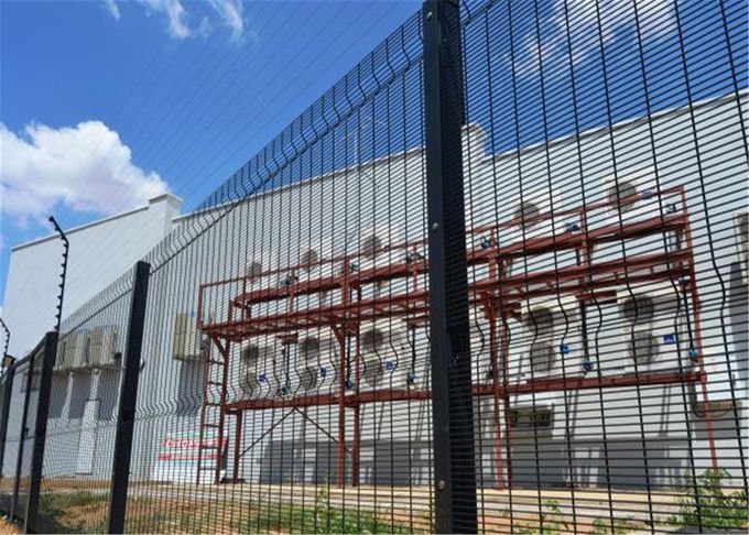 |
| Original BMP panel photo: verify installed panel alignment, position, and consistency with the selected support design. |
Avoid trimming factory-coated panels merely to force a bay into an incorrect opening. Cutting can expose bare steel and damage protective finishes. Factory-made closing panels provide a cleaner documented solution.
If an approved field modification becomes necessary, follow the coating-repair specification. Recheck wire ends and sharp edges before handover. Unauthorised modification may affect warranty coverage.
The attachment system connects the mesh to its supports and transfers service loads. Confirm whether each connection needs a single clamp or a double clamp. Corner posts and terminations may differ from intermediate supports.
BMP ClearVu Fence Clamps include model-specific plates and bolt arrangements. A 50 × 76 mm plate appears in one single-bolt reference. Another double-bolt plate measures 50 × 165 mm.
| Attachment location | Required action | Inspection point |
|---|---|---|
| First end post | Use the approved end-clamp configuration | Check panel edge and bolt engagement |
| Intermediate post | Fit the specified connection for adjacent panels | Confirm spacing and correct clamp count |
| Corner or change in direction | Use the corner hardware shown on the drawing | Check face orientation and secure engagement |
| Special gate transition | Follow the gate connection detail | Check clearance from moving components |
| All security bolts | Tighten to the approved manufacturer value | Check anti-vandal drive and coating condition |
Install and position all required clamps before fully tightening the connection group. Keep each panel aligned while adjusting fasteners. Follow specified bolt torques rather than applying maximum available force.
Overtightening may deform plates or damage coatings. Under-tightening can leave movement at the mesh edge. Record fastener checks during final inspection.
Continue through the marked bays while checking every post for alignment. Compare the next panel with the same top reference and ground-clearance requirements. Keep protective materials away from sharp edges.
At corners, inspect actual turning angles and clamp interfaces. A site that changes direction may need special plates or adapted bay lengths. Do not bend a rigid panel around the corner.
End posts restrain one final edge rather than an ordinary pair of adjacent panels. Gate supports carry additional moving loads and may need larger footings. Their drawings should remain separate from the repeating fence bays.
BMP Clear View Fence Gate options include pedestrian and vehicle arrangements. Align the infill with the adjacent fence where specified. Confirm latches and emergency access requirements.
Gates need accurate openings, properly aligned frames, and safe travel clearances. Install hinges, stops, locks, and guides in the sequence provided by the gate manufacturer. Test movement before commissioning any powered equipment.
A ClearVu Fence Sliding Gates assembly may require dedicated rails, rollers, guides, and foundations. Motorised gates need appropriate safety devices. Never assume ordinary line posts can support moving gate loads.
Keep mesh edges clear of the moving gate envelope. Protect pedestrians from entrapment points and vehicle movement. Electrical work should follow applicable regulations and competent installation practices.
Verify manual release functions and locking arrangements during commissioning. Drainage around ground tracks also matters after heavy rain. Gate documents should identify the maintenance intervals.
Complete the chosen post caps after inspecting open tube ends. Caps can reduce debris and moisture entry where the design requires them. Their attachment method must match the post specification.
Optional toppings require separate safety, legal, and loading reviews. Sharp items or energised accessories do not belong on every project. Consider public pathways, maintenance access, and emergency routes.
Use coated tools or protective contact pads where appropriate. Scratches near clamps and post caps may expose bare steel. Repair approved damage with compatible materials and recorded procedures.
Related Powder Coated Clear View Fence finishes need their particular repair instructions. A matching colour alone cannot restore zinc protection. Inspect edges before final acceptance.
Durban and Cape Town projects can face salt-bearing air and humid weather. Corrosion protection needs particular attention around cut edges and fasteners. Cleaning and inspection should match actual exposure.
Johannesburg and Pretoria installations face more inland dust and seasonal rainfall. Stormwater can affect post surroundings and sliding gate tracks. Keep drainage functional and check fixings after major weather events.
A High Security ClearVu Fencing panel may use different wire sizes from wider mesh options. Coating choices likewise depend on the exposure and contract. Avoid swapping finished parts onsite without approval.
BMP ClearVu Fencing for Sale includes compatible post and clamp examples. Select one coordinated material schedule. Confirm the manufacturer's written warranty for the actual supplied system.
Inspect the entire boundary after all permanent connections and caps are complete. Check posts, mesh edges, gate openings, coating repairs, and drainage. Record any defects before handover.
| Inspection area | Required check | Acceptance evidence |
|---|---|---|
| Fence alignment | Posts remain plumb and panel tops follow approved levels | Survey measurements and photographs |
| Concrete foundations | Released for loading under the approved strength criteria | Concrete records or engineer approval |
| Panels | No unapproved cuts, missing welds, or excessive distortion | Visual inspection and drawing checks |
| Clamps and bolts | Correct location, quantity, engagement, and torque | Connection checklist |
| Gate function | Smooth travel, reliable locks, and safe operation | Functional test record |
| Coatings | No unacceptable scratches, exposed steel, or failed repairs | Coating repair log |
| Handover | Site clear, documents complete, maintenance instructions supplied | Signed completion record |
Permanent ClearVu systems use engineered foundations, rigid panels, and compatible security attachments. Some projects need an alternative barrier during construction. These products have different installation and stability requirements.
Portable Temporary Construction Fencing uses removable supports for changing work areas. By contrast, Garrison Security Fencing uses vertical pickets and rails. Their assembly procedures differ from ClearVu mesh.
Another system, Corromesh, has its own formed mesh and fitting details. Do not assume identical clamp positions. Verify each manufacturer's documentation independently.
Use the approved panel-and-post drawing to mark actual centres. Check the first few bays and the final endpoint before concreting. Never substitute a nominal panel width for this dimension.
Not automatically. Concrete strength develops at different rates under different conditions. The approved strength criteria determine when panels may load the supports.
No universal gap applies to every connection. Fixed clamps and panel edges need their specified clearances. Follow the approved assembly details instead of adding an arbitrary opening.
The footing design depends on height, wind, soils, post geometry, and local requirements. Some BMP drawings show 600 mm references. The site engineer confirms actual dimensions.
Many systems use bolts and clamps without site welding. Gates or special details may require other approved work. Any welding needs suitable coating restoration and technical approval.
Use the supplied components and follow the approved installation requirements. BMP offers a 15-year manufacturer warranty for applicable ClearVu products under written terms. Keep inspection and maintenance records.
Boss Metal and Plastic Co., Ltd. supplies welded fence panels, steel posts, fittings, and gates for export projects. Buyers should send the surveyed layout, chosen mesh, post system, and local foundation requirements. A complete schedule helps installers avoid incompatible parts.
Regional ClearVu Fence Panels provide another BMP product reference with its own configurations. Compare approved drawings before ordering. Record delivery and installation responsibilities in the final agreement.